
Protecting Power Inputs on Circuit Boards
Introduction
When I first started designing circuits, I found it surprisingly difficult to find information on protecting the main power supply input of a circuit board. I thought it was strange, since it seemed like such an important part of circuit design. Early on, I either simply added a fuse or ignored it entirely. Over the years, I encountered boards that were damaged, as well as boards that had to undergo proper surge and EFT testing. Through these experiences, I learned that input protection is indeed important and must be considered.
The goal of this article is to outline the three most common types of events that can damage a board: reverse polarity protection, overvoltage protection, and overcurrent protection, and what can be done to prevent them. I will start with simple, inexpensive methods for each, then cover a component that can handle all three, which we use in many of our designs when size and budget allow.
This article is not meant to be an all-encompassing guide to every type of input protection, nor does it cover all possible solutions. It focuses on practical and easy to implement solutions. Surge testing, isolation considerations, and other advanced methods will be covered in a separate article.
Reverse Polarity Protection
Reverse polarity events are among the most common issues in consumer electronics and in any application where the user connects the power supply, especially in battery-powered devices. Depending on the circuit, some components can survive reverse polarity without damage, while others can fail instantly from even a small amount of negative voltage.
Series Diode
The simplest form of reverse polarity protection is to place a diode in series with the supply. The diode allows current to flow in one direction while blocking reverse voltage entirely.
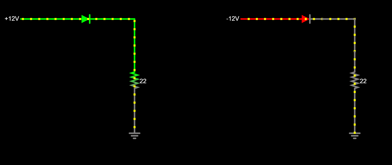
The drawback is the constant voltage drop across the diode. As current increases, power loss also increases. This approach works for low-power circuits connected to wall supplies, where efficiency is not a major concern. In battery-powered systems, wasted power shortens runtime. High-power circuits are also impractical, as the diode must be large and will dissipate significant heat.
At 500 mA, a standard diode with a 0.7 V drop will dissipate 0.35 W continuously. A Schottky diode reduces the drop to around 0.2 V, lowering dissipation to 0.1 W at the same current.
P-Channel MOSFET
A more efficient reverse polarity protection method is to use a high-side p-channel MOSFET. This eliminates the constant voltage drop, replacing it with a very low RDS(on) that dissipates far less power. For example, an RQ3E100ATTB with an RDS(on) of 11.4 mΩ will dissipate less than 6 mW at 500 mA, while handling much higher current.
For a deeper dive into MOSFET circuit design and selecting the right MOSFET for your application, check out our dedicated articles on those topics.
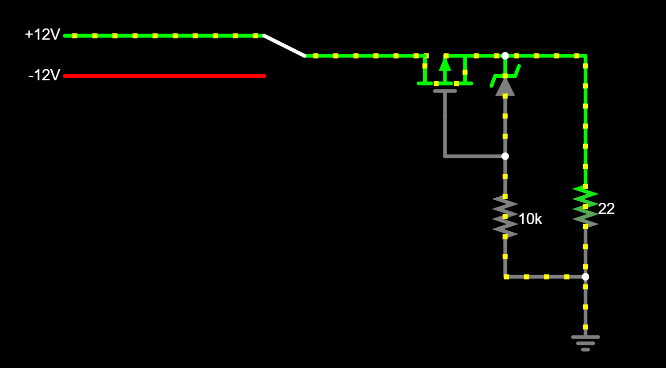
A Zener diode is used to ensure the MOSFET’s maximum gate-to-source voltage is not exceeded. The series resistor should be sized so it does not cause excessive dissipation when the Zener conducts.
Overvoltage Protection
Overvoltage events can occur when an incorrect power supply is connected or from surges and transients on the input. Some parts can tolerate short overvoltage spikes, but many cannot.
One of the simplest overvoltage protection methods is to use a fuse, either a single-use fast-blow fuse or a PTC resettable fuse combined with a Zener diode. If the voltage exceeds the Zener’s clamp voltage, it creates a short to ground, causing the fuse to blow. For standards-level surge protection design, see our article on IEC 61000-4-5 surge protection circuits.
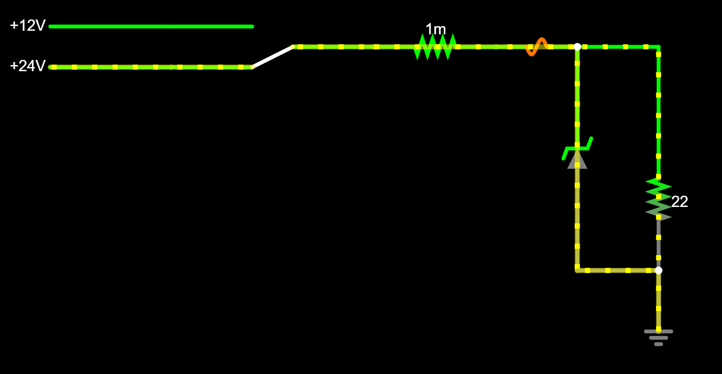
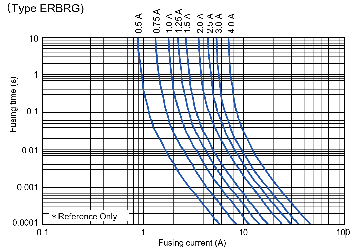
When selecting a fuse, understand its time-current characteristics. It must blow before the Zener diode overheats.
Be cautious if the supply is current limited. If the supply limits current below the fuse’s blow threshold, the Zener may overheat without the fuse ever opening.
Overcurrent Protection
In a properly designed circuit, an overcurrent event at the main input should be rare because outputs should have their own protection. However, shorts can still happen, for example, if a tool or component falls onto the board during testing.
The simplest overcurrent protection is an inline fuse. The same considerations as in overvoltage protection apply. When paired with a Zener diode, the same circuit can protect against both overcurrent and overvoltage events, which is why we rarely use a fuse alone.
Bulk Capacitance
Bulk capacitance, typically from large electrolytic capacitors at the power input, helps suppress transients, reduce noise, support voltage during brownouts, and improve overall stability.
However, if the capacitor is connected directly to an already-powered supply, hot-plugging can cause inrush currents in the tens or hundreds of amps. USB and other standards limit bulk capacitance to prevent damage to upstream devices.
The simplest mitigation is to use a supply that can handle inrush current. If the board is always connected before power-on, this is not an issue. eFuses, covered next, can also address inrush concerns.
eFuses
Overview
An eFuse can provide reverse polarity protection, overvoltage protection, and overcurrent protection in one device. Texas Instruments is the most well-known manufacturer, though others produce similar devices.
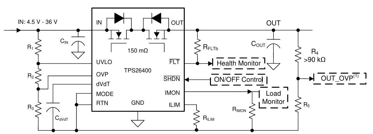
They use back-to-back N-channel MOSFETs controlled by internal logic to protect against multiple fault types, while also offering inrush control, undervoltage protection, and diagnostics. Some parts have built-in reverse polarity protection; others require an external component.
Search Tool
Texas Instruments provides a search tool to select eFuses by parameters such as voltage range, current limit, and MOSFET configuration.
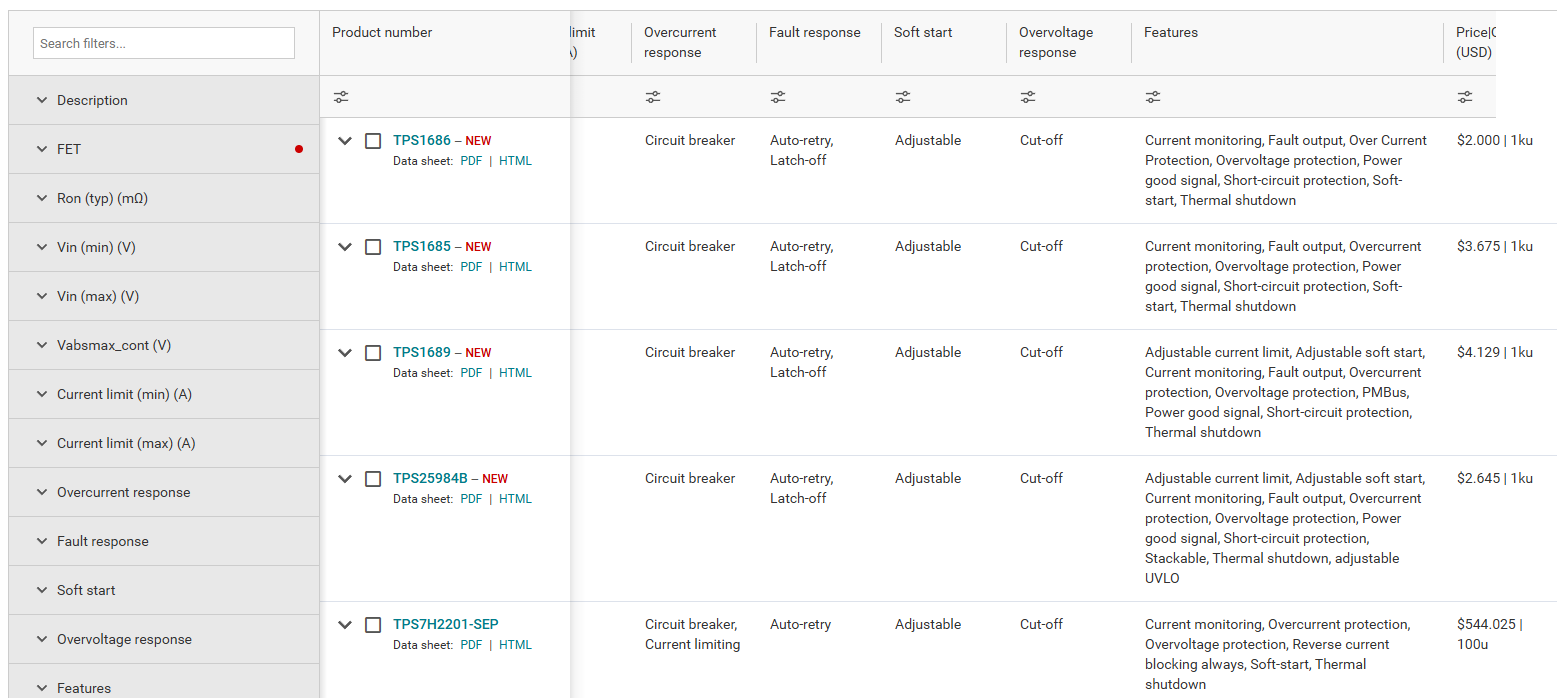
Overcurrent response can be set to either circuit breaker (disconnecting the load) or current limiting (holding current at a set point until shutdown). Fault response can be auto-retry or latch-off. Soft start settings control inrush current.
Implementing in Your Design
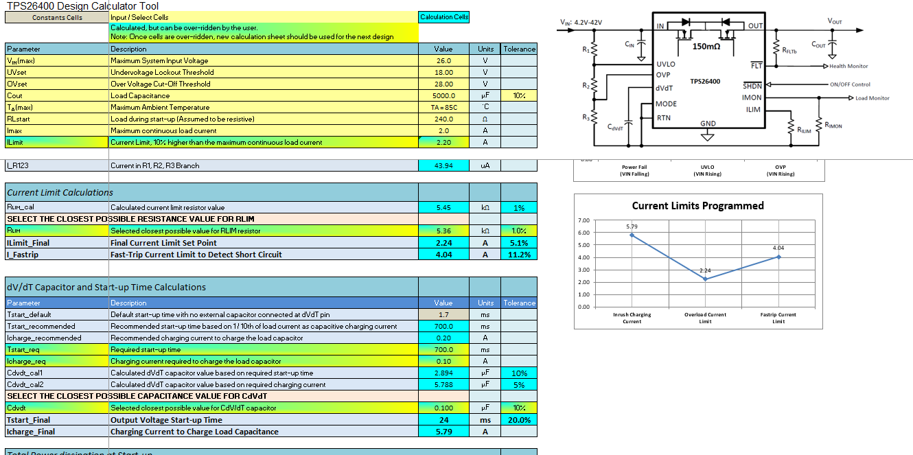
Some passives in eFuse designs, such as the resistor ladder for voltage thresholds and the dv/dt capacitor, can be difficult to size manually. TI provides Excel-based calculators to simplify selection and estimate inrush current, startup time, and thermal performance.
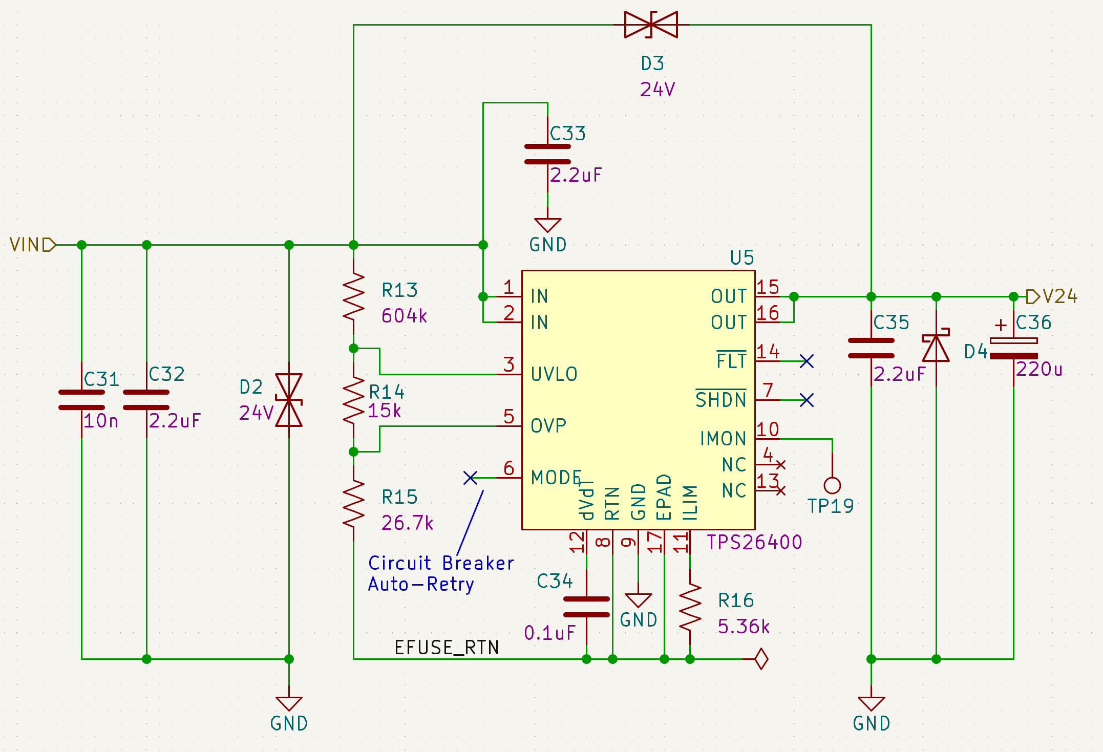
While these eFuses can be used with minimal external parts, it often makes sense to add additional protection. In Figure 8, I show an example of how we implemented an eFuse in one of our industrial product designs.
In this design, the eFuse can handle an input range from -42 V to +45 V. If a large voltage transient occurs, D2 will clamp the voltage to ±38.9 V, keeping it within the allowable range for the eFuse. Depending on the surge energy, D3 may shunt additional power across the eFuse, helping prevent damage to either the eFuse or D2.
D4 is included to protect against large downstream inductive spikes that could be negative. Additional downstream bulk capacitance at C36 helps “soak up” extra surges and transients that pass through the eFuse.
Conclusion
Protecting a circuit board’s power input is essential for long-term reliability. Reverse polarity protection, overvoltage protection, and overcurrent protection can be implemented with simple discrete components or with integrated solutions like eFuses. Understanding the tradeoffs between cost, complexity, and performance will help you choose the right method for your application.
Advanced topics such as surge protection testing, isolation considerations, and compliance with standards will be covered in a future article.
MicroType Engineering specializes in designing reliable, fault-tolerant electronics for demanding applications. Whether you need reverse polarity protection, overvoltage protection, or overcurrent protection designed into your PCB, our team can help ensure your products perform flawlessly in the field. To learn more about our services and how we can support your next project, please reach out!


.webp)