
Why Standardized Outputs Matter
One of the things released in KiCad 9 that doesn't get talked about much is jobsets. In a nutshell, jobsets allow you to configure a list of project/fabrication outputs that are all generated with a single click. For our workflow, this has honestly been game-changing.
A bit of context: we're a design and assembly shop, but exclusively contract work, no OEM products. Everything we do is for external companies. That means we don't have the luxury of working on one project for years; depending on the year, we're working on 10+ projects at any given time. Some years we will complete 30 or 40 different design projects.
When you're manually exporting things, it's really easy to forget something or use slightly different parameters than you intended. Maybe you forget the drill files. Maybe you use the wrong coordinate format on your centroid. When you're juggling multiple projects, it's not a matter of if; it's when. Standardizing the way you handle inputs and outputs from the tool is critical.
Our Workflow Integration
When jobsets were released, I wrote a tool for us to use called MTKiCad. It uses the KiCad CLI (kicad-cli), the jobset CLI functionality, and native KiCad Python plugins. I also use the Interactive BOM plugin and some string matching with the S-expression format that KiCad files use natively.
I'm going to try and keep the information on MTKiCad as limited as I can in this post as I want to focus more on jobsets. But I'll reference MTKiCad as a frontend to show how we use jobsets in practice. Everything I show can also be done through the native KiCad interface or kicad-cli, so don't worry if you're not using any custom tooling.
Project Structure
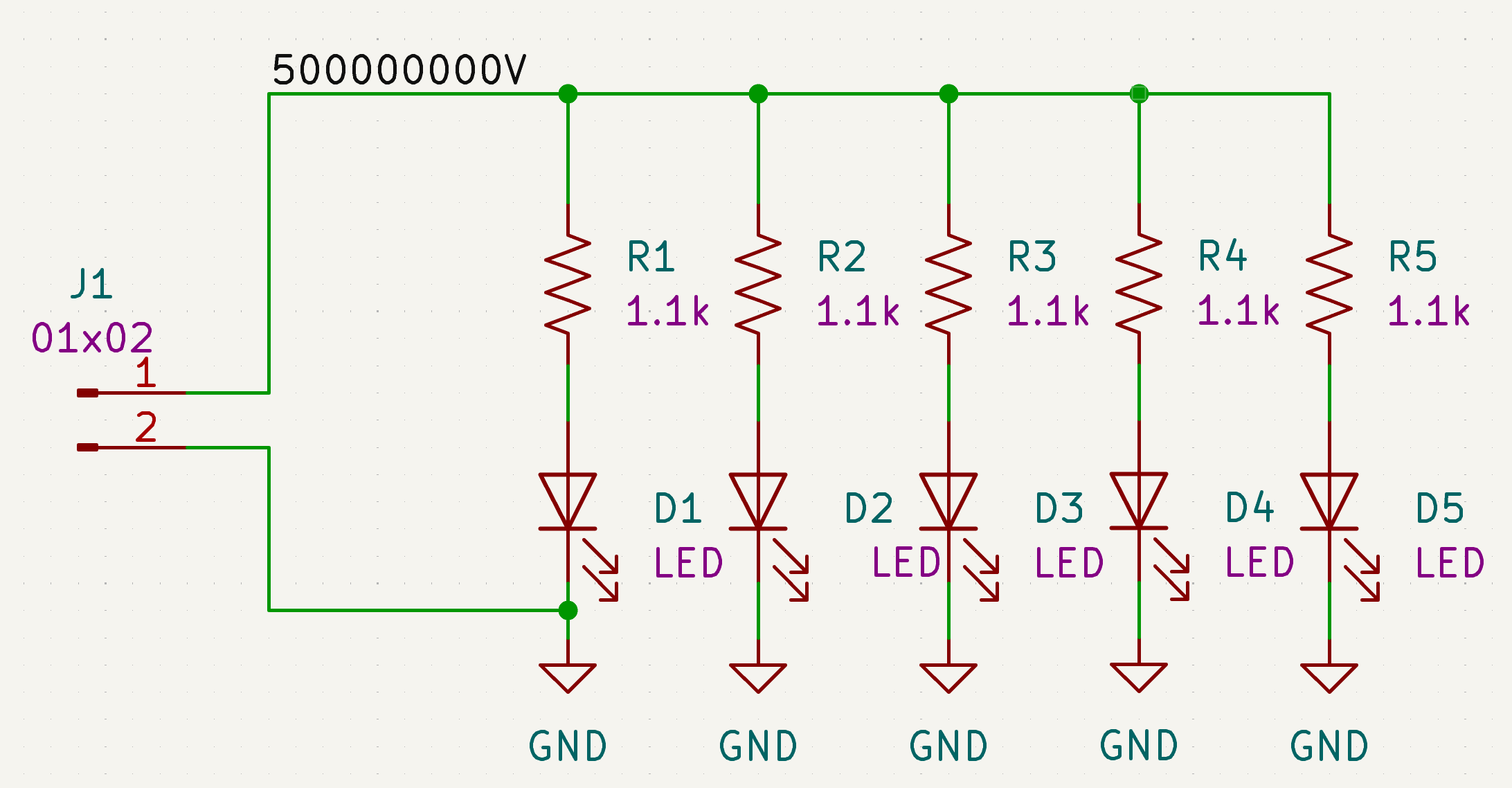
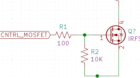
For this example, I'm using a project called "Photon Cannon." Wait till you see the schematic, I'm giving away all the secrets on how to make one!
Within the project structure, I have a list of all boards (for this example just a single main board). Within boards/ there's a design folder for all the design files, a manufacturing folder for panel configurations, and an outputs folder. The outputs folder is where everything generated from jobsets lives: fabrication files, panel files, PCB outputs, and schematic outputs.

Figure 2: Project folder structure showing the outputs directory. All of this gets generated from the jobsets.
Schematic Outputs
In our workflow, once we finish a schematic, we do an internal design review and then an external design review with our customer. For each of those, it's mandatory to have proper schematic outputs to share and review.
Running through our tool, we call mtkicad schematic and it prompts for the revision number. We start at 0.1-pre, where "pre" implies it's never been released yet. The revision is purely a labeling convention for tracking design iterations—it updates text variables in the title block's and silkscreen but doesn't interact with Git or any version control system directly. We handle Git commits and tagging separately as part of our release workflow.
The schematic outputs go into outputs/schematic, and include four files:
- BOM CSV: A standard bill of materials exported using KiCad's built-in BOM generator
- ERC Report: Footprint issues, library reference issues, and similar checks from the Electrical Rule Check
- PDF: By far the most useful output for design reviews. In a capable PDF viewer, it's a plotted file so you can click on individual components
- Netlist: Used during DFM review to compare against the generated netlist and verify they match
PCB Outputs
Once the schematic is done and we move to layout, the workflow is the same: internal and external reviews. Instead of schematic, we run mtkicad pcb with the same revision prompt.
This one takes longer to run because the PCB outputs include rendering PNGs. Rendering, no matter what computer I've tried it on, is a pretty time-intensive process.
The PCB outputs go into outputs/pcb and include:
- STEP file: For mechanical integration, exported as a 3D model
- DRC Report: Design rule check results
- Renders: Multiple angles for both top and bottom of the board using the raytraced render job
Fabrication Outputs
Fabrication outputs are probably the most important to most people. We use schematic and PCB outputs for team reviews, but for a traditional workflow where you're not doing extensive reviews, exporting Gerbers, centroid files, and ODB++ is the core use case. These outputs feed directly into our PCB assembly workflow.
Running the fabrication command kicks off six jobs:
- Gerber files: Including drill files
- Centroid top and bottom: Even if the board doesn't have bottom components, it exports both. These position files are essential for pick and place machines during assembly.
- Interactive BOM: Super helpful for hand placing or inspection. Uses the iBOM plugin, which can be run through jobsets using the Special: Execute Command job type
- IPC-2581 file: Using the IPC-2581 export format
- ODB++ file: Using the ODB++ export format
- Do-not-place list: A custom markdown file listing DNP parts
Our tool also handles panelization with KiKit and release scripts for Git, but I'm not going to get into those here since they don't really touch jobsets.
Configuring Jobsets
Now for the actual jobset configuration. To create a new jobset, use File > New Jobset File in the KiCad project manager. Jobset files (.kicad_jobset) are stored in your project directory and appear in the project file tree.
Figure 3 shows the main jobset screen. On the left side, you get a list of all the jobs, where each one is essentially just an individual task that runs. On the right side, you have your destinations, which define a list of jobs to run and how to store their outputs.
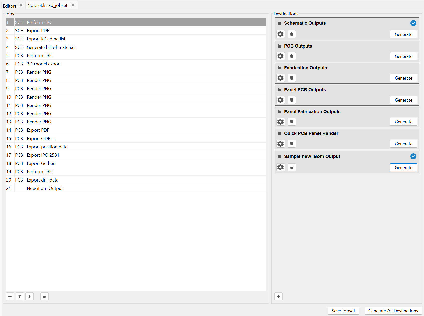
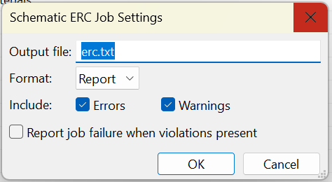
For each job type, the settings are more or less the exact same thing you'd get if you went to the screen from the normal GUI. Figure 4 shows an example with the ERC job settings. If you've exported Gerbers or run an ERC manually, everything should look pretty familiar.
Available Job Types
KiCad supports a wide variety of job types out of the box. The key ones I use are:
Schematic jobs:
- Export PDF, DXF, SVG, or PostScript plots
- Generate Bill of Materials
- Export Netlist (various formats)
- Perform ERC with optional failure reporting
PCB jobs:
- Export Gerbers, drill data, and position files
- Export 3D models (STEP, GLB, STL, etc.)
- Export IPC-2581 or ODB++
- Render raytraced PNG/JPG images
- Perform DRC with optional failure reporting
Special jobs:
- Copy Files to specified locations
- Execute Command for running arbitrary scripts or plugins
The Execute Command job is particularly useful for integrating external tools like Interactive BOM into your workflow.
Destinations
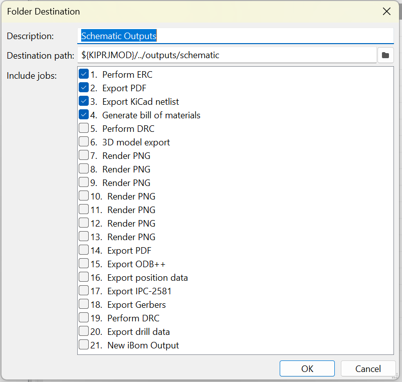
It is important to note how destinations work. When you click the gear icon on a destination, you get the dialog shown in Figure 5. This is where you set the output path and select which jobs to include. Since each destination has its own path, you can organize your outputs however you want.
Destinations can output in two modes:
- Folder: Saves outputs uncompressed in a directory
- Archive: Saves outputs to a compressed zip file, which is convenient for sending fabrication files to your manufacturer
Output Paths and Text Variables
The biggest gotcha here is paying attention to where the output file goes. If you don't have any nested directories specified in the job's output file field, it's going to output at the top level of wherever your destination is.
For schematic outputs, we have ERC, PDF, netlist, and BOM all going to outputs/schematic, all top level in that folder. For PCB outputs, everything goes to outputs/pcb, but the renders have a subfolder specified (you can see "renders/top-iso2.png" in Figure 6) so they get collated into outputs/pcb/renders.
You can use text variables in your output paths, which is helpful for keeping things organized:
- ${PROJECTNAME} - The project name
- ${CURRENT_DATE} - Today's date
- Any project text variables you've defined in schematic setup
Render Configuration
The PNG renders are kind of a pain to configure because you have to figure out what positioning and zoom level you want. Figure 6 shows all the options you get. When I set this up, I essentially just guess-and-checked until the output looked right. There's no preview; you just have to run it and see what you get.
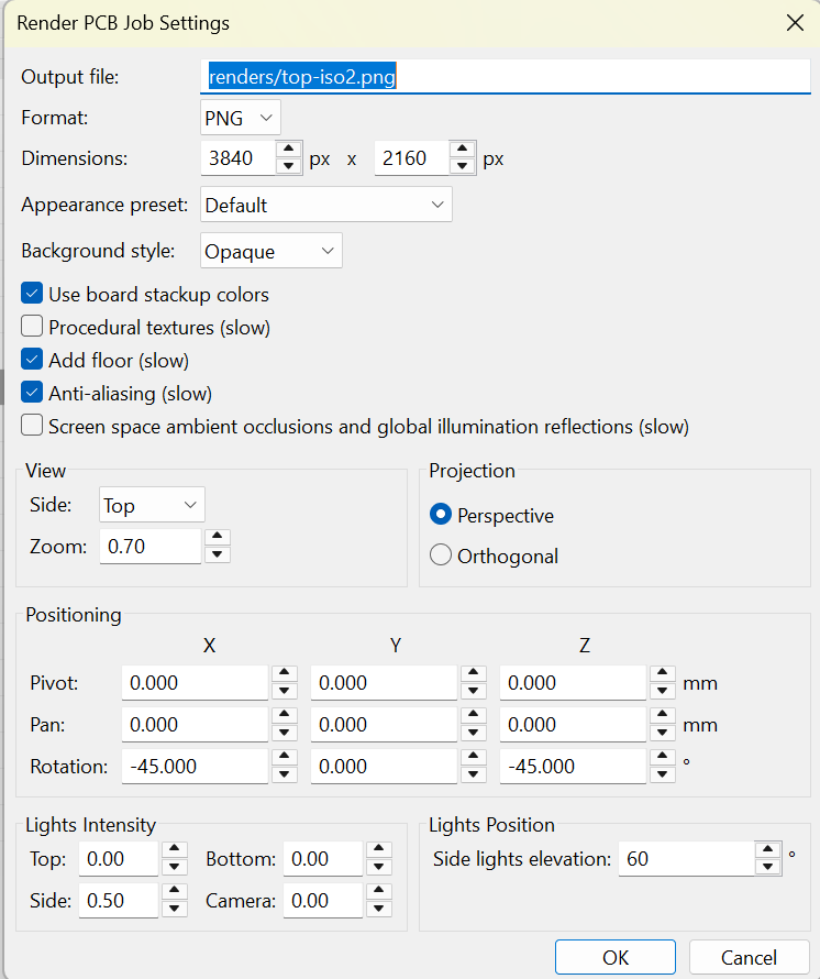
I have six different render jobs configured for different angles. It took me a while to dial them in, but once it's set up you never have to think about it again.
Reusing Jobset Configurations
Jobsets don't have to live in your project directory. We keep our main jobset file in a central location (our shared KiCad libraries repo). When you open a jobset file (whether from the GUI or CLI) it automatically uses the currently open project as its target. The jobset itself just defines what project/fabrication outputs to generate and how. All the project-specific context comes from whatever project you have open.
In the GUI workflow: open your project normally (like you would to edit the schematic or PCB), then use File > Open Jobset File to open your shared jobset from wherever it lives. When you run it, KiCad uses the open project for all the outputs.
In our CLI workflow, MTKiCad does the same thing, it always runs the jobset from our central libs repo. It then just points to the local project as the target.
This means you configure your jobset once, store it somewhere accessible, and use the same configuration across every project. No copying, no per-project setup.
Running Jobs and Viewing Results
You can run any destination directly from the configuration screen by clicking the Generate button, or run everything at once with Generate All Destinations. The output is essentially the same as running from the command line.
After a destination runs, KiCad shows a status indicator: a blue check for success or a red exclamation for failure. Clicking on this indicator opens the Jobset Run Log dialog, which displays the status of each job and any logged output. This is helpful for debugging when something goes wrong.
Gotchas and Tips
A few things to watch out for.
Renaming jobs: In the past, renaming jobs here and then saving it wouldn't actually save. I don't know if this is still a bug, but that's why even where I have duplicates, I keep them named the same way.
CLI usage: If you use the command line interface, the command to get what the name of the job is can be kind of annoying. You can't just call it by the name or description here; you have to call it by its unique ID. You can't get that ID directly from the interface, you have to look in the jobset file itself. In MTKiCad, I just have a lookup function that searches through and grabs it so I can call jobs by name and have it reference the correct ID automatically.
Execute Command and temporary paths: When jobs run, output files are initially generated in a temporary folder, then moved to the destination after all jobs complete. If you're using Execute Command to run scripts that need to access other job outputs, use the ${JOBSET_OUTPUT_WORK_PATH} environment variable to reference the temporary location.
Conclusion
So yeah, that pretty much covers everything with jobsets. They solve a problem that's easy to underestimate until you've forgotten drill files on a Friday afternoon. Set it up once, configure your outputs the way you want them, and then it's just one command every time. Same settings, same file structure, no guesswork.
For shops like ours that are juggling dozens of projects a year, this kind of standardization is essential. But even if you're just working on a single project, the consistency alone is worth the setup time.
Here at MicroType Engineering, we've integrated jobsets into our standard workflow for all new projects. If you have questions about KiCad workflows or need help with your PCB design process, don't hesitate to contact us.


.webp)