
H-Bridge Circuit Basics
What is an H-Bridge circuit?
In the most simplistic terms, an H-bridge circuit can switch the polarity of the attached load. The most common use of an H-bridge is to drive a DC motor, allowing directional control. There are various H-Bridge designs, and some use discrete components consisting of MOSFETs, while other designs utilize a dedicated Integrated Chip (IC) H-bridge.
How does it work?

Figure 1: Simplified diagram of an H-Bridge circuit (in red) driving a DC motor. Image: Cyril BUTTAY [CC BY-SA 3.0], from Wikimedia Commons
Figure 1 shows a basic high-level view of an H-bridge circuit controlling a DC motor. When S1 and S4 are closed, the motor is powered and spins in one direction. If S3 and S2 are closed, the motor changes direction and now rotates in the opposite direction. If all switches are open, or only a single switch is closed, the motor will have no power, and will “coast.” If both S1 and S3 are closed, or S2 and S4 are closed, the motor is powered to resist motion and will brake if currently spinning.Care must always be taken to ensure a “shoot-through” condition never occurs. This condition occurs when S1 and S2 are closed, or S3 and S4 are closed. An immediate short circuit results, and can destroy the rest of the circuit, causing the magic white smoke to appear. Many H-Bridge circuits have protection to prevent a “shoot-through” condition from occurring, but it is still best to ensure that it will not arise programmatically.
Discrete components vs. Integrate Chip (IC)
Discrete components
The traditional method of constructing an H-bridge is by using discrete components, typically MOSFETs to act as the four switches as shown in figure 2. This allows for great flexibility in choosing the parameters for the circuit. Additionally, these can be cheaper than a dedicated H-bridge chip (when you add in the features of some ICs, this is no longer the case!). It is important to note, that figure 2 only shows the basics outline of a discrete component H-bridge circuit. It would need additional circuitry to allow for proper and safe operation.
For more on designing with power MOSFETs and choosing the right MOSFET for your application, check out our dedicated articles.
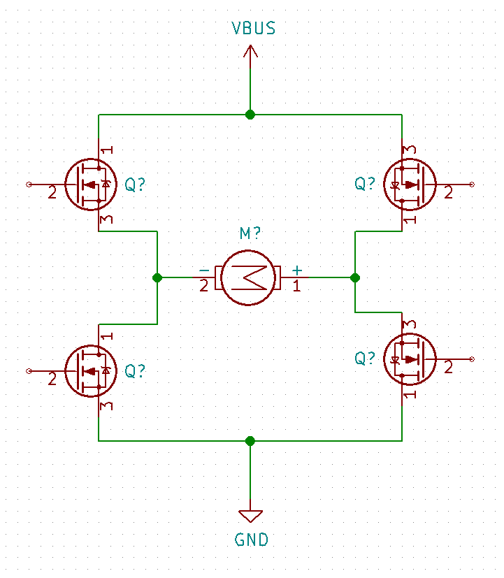
Figure 2: Basic layout of an H-Bridge circuit using discrete MOSFETs.
Integrated Chip (IC)
The circuit I will be showing today is based on an integrated circuit H-bridge, specifically a Toshiba TC78H620. In my opinion, for the majority of use cases, it is better to use an IC when one is available. This is especially the case when designing an H-Bridge circuit. The number of features that a modern IC contains, along with the reduced design time and part count make the usage of ICs quite attractive. For example, the TC78H620 contains over-current detection, thermal monitoring/shutdown, and undervoltage lockout. At quantities of 2000 parts, they are available for around $0.60 each. Some ICs will contain circuitry to help protect from inductive loads, but the TC78 does not.
Implementing the H-Bridge Driver
The main topic of this video is to discuss the implementation of an H-Bridge IC in a schematic and printed circuit board (PCB) layout. The software used is KiCad 5.0. One of the main advantages of using an integrated H-Bridge is the simplistic nature of the external circuit. Other than accounting for flyback spikes due to the inductive nature of DC motors, there are few external parts.
Inductive flyback protection
Flyback diode basics
The most important item to understand when driving a DC motor is that it acts as an inductive load. Once power is supplied to the motor, it stores energy in a magnetic field. Once the motor is up to speed, the stored energy is at a maximum. When power is removed, the magnetic field collapses. This field then tries to keep the amount of current flowing constant. The only way it can do this is by increasing the applied voltage across the terminals of the motor. This voltage can be many times the supplied voltage used in the circuit. If there is no safe way to dissipate this within the circuit, this voltage can destroy the circuit. The induced voltage is always the opposite polarity of the applied voltage.
The most common way to handle this voltage spike is to use "flyback diodes." These aptly named diodes are typically just standard diodes, rated at many times the supplied voltage. These are used to create a pathway for the inductive voltage spike to go.
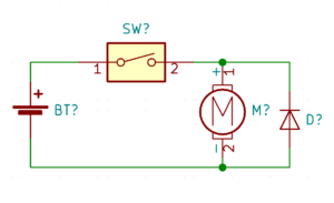
Figure 3: Example of a unidirectional motor with a flyback diode
Figure 3 shows a simple example of a flyback diode with a power supply that does not change polarity. The motor spins when the switch closes. The diode becomes reverse biased, and current flows through it. When the switch opens, the induced voltage reverses direction and can flow through the now forward biased diode, as shown in figure 4.
Figure 4: Path of the inductive flow through the flyback diode
H-bridge circuit flyback diode implementation
Unfortunately, when using an H-bridge circuit, a single flyback diode will not suffice. Since there are multiple current pathways, there must be four diodes to provide a path for the induced voltage as shown in Figure 5. No matter the direction of the motor or the induced voltage, it always has a safe pathway to go through the power rail.
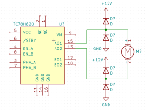
Figure 5: TC78H620 H-Bridge circuit with flyback diodes
Bringing it all together
Now that we have handled the inductive load issue, the rest of the circuit is quite straightforward. For this circuit, it is intended to be a standalone board, using an external microcontroller such as an Arduino or Raspberry PI. Figure 6 shows the completed circuit, using global labels to connect the majority of the nets from one component to the other. There is a small decoupling capacitor, C1, that will be placed close to the H-Bridge on the PCB. There is also an (optional) large electrolytic capacitor, C2, that helps to store energy to supply to the motors. This capacitor can also help to dissipate some of the flyback voltage that passes through the diodes.
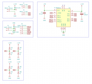
Figure 5: Completed H-Bridge circuit with flyback protection
Conclusion
Since this is a simple circuit, I will not go over the PCB layout in this post, as my implementation is in part two of the video series. This post covered the basics of what an H-Bridge circuit is and the various ways in which they can be implemented. For the circuit created here, we used an integrated H-Bridge, which allows for a more simplistic design, with fewer external parts required. Since the IC chosen had no protection from inductive loads, we discussed the proper way to protect the circuit.
MicroType Engineering designs custom motor drivers and motion control systems. If you need help with an H-bridge or power electronics design, contact us to discuss your project.


.webp)