
Why is this article needed?
I remember back when I first began designing electronics as a hobby. I would only use an Integrated Circuit (IC) that I could find a tutorial or guide for. It was terrifying for me to read through the massive datasheets that all IC’s have! I think that a lot of people struggle with this as well. Even today, after having used hundreds if not thousands of different IC’s, I still run into issues understanding and reading datasheets. In fact, in my community Discord channel I often post an image of what I call the “bad datasheet of the day!”
When choosing parts, you want to have a standardized process when reading a datasheet. The goal of this article is to highlight the process that I use. I will offer some global tips and tricks for nearly all datasheets you will encounter. To do this, I will be referencing the datasheet for a new Buck DC/DC convertor by Visay, SiC45x. (Side note: Expect a future video/post about designing with this IC!)
Where to begin when reading a datasheet?
As funny as it may sound, the absolute first place I start with nearly any datasheet is the “Typical Application Circuit.” Often, if a datasheet doesn’t include one, I will not use that IC. This example schematic gives a really good, quick overview of the IC in an actual design. It also let’s you know how many external components it requires.
A common exception to this rule is with microcontrollers (MCU's). Since they are so complex and diverse, there really isn’t a typical use case. Instead, they will include different, smaller schematic’s of important blocks. Decoupling, oscillators, and programming connectors are all commonly shown. Bonus points go to an MCU datasheet that also includes a schematic of the minimal hardware connections. (Sometimes they will have a separate document titled “Hardware Considerations”)
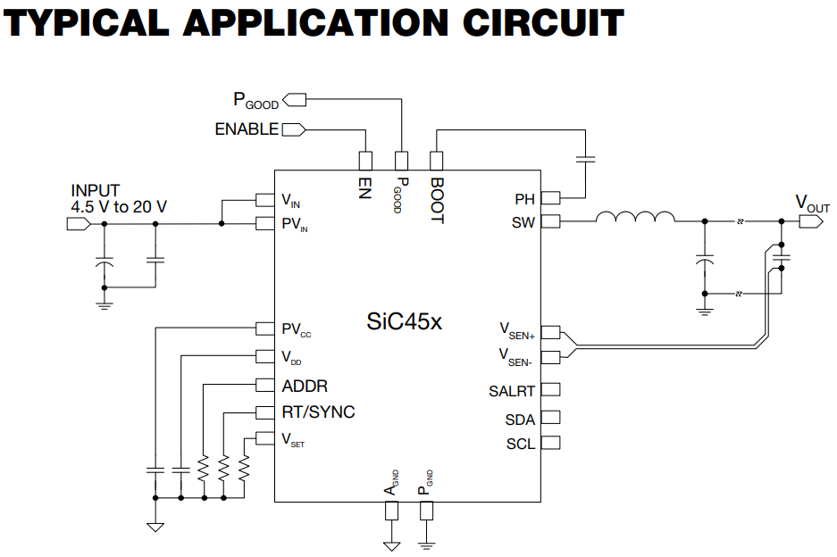
Figure 1 shows the typical application circuit for the SiC45x. Having no other knowledge about this IC, we are able to learn:
- The input range is 4.5V – 20V.
- Since we do not see any external FET’s, we know that they are internal to the part. (Impressive on such a high-powered regulator!)
- It allows register writing and reading over i2c, and allows the address to be changed.
- Since there is a RT/SYNC pin, when know that we can adjust the frequency.
- Based on the number of bootstrap/status pins (ENABLE/PGood/SALRT), it may be able to be used without i2c.
Of course, that’s not all the information we need to design, but it’s a pretty good place to start!
Read both part descriptions
Something that is a bit funny when reading datasheets, is how repetitive some are when describing the part. At the very top of the document they will have a section called the “Description.” This is a good place to get a good overall feel for the part, and what it does. A few pages below, usually past the pinout, ratings, and block diagram, there is the “Operational Description.” This is exactly what it sounds like. The first section of this will typically reword the original description, adding some more details.
Past this first section, there is typically a bunch of different sections within the operational description. These describe different functional “blocks” of the IC. Not all datasheets have this, but most semi-complex parts do. It is an incredibly useful section when you are working on your design. I typically only skim it initially when choosing parts. When working on the actual schematic, I constantly will reference this section. The majority of equations and other settings will be in these blocks.
Check the absolute maximum values!
Once I have examined the example schematic and read the descriptions, I then move straight to the section on the absolute maximum values. Often, right below that section there will also be “Recommended Operating Conditions.” I will check both tables, ensuring that I do not plan tot exceed these ratings. Typically I am looking for the maximum voltage on each pin, and the maximum current that the IC/pins can source/sink.
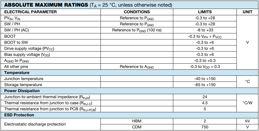
Looking at figure 3, we see the SiC45x’s absolute max ratings. It is crucial to understand that these ratings are not necessarily what it should/can be operated at. It is instead a guide to what you should never subject the part to. For example, the absolute max input voltage is listed at 28V. The recommended operating conditions state the maximum rated voltage is actually 20V. I would not run this part from a 24VDC supply. I would, however, run it at 20V, with an upstream overvoltage protection scheme clamping the voltage to 24V. If there are some momentary 24V transients, the part should be OK.
Understand the pinout table
So at this point I have a decent understanding of how the IC operates and its basic connections. I also know from looking at the absolute max ratings, that it will work under the conditions I need it to. The next place I usually check is to look at the “Pinout Table”. It is sometimes also called the “Pin Description”. The short description beside each pin is incredibly useful as a reference. When I’m designing a circuit with an IC, the pin description table is one of my most commonly used references that I check back to. It is typically located in-between the example circuit and the absolute maximum ratings.
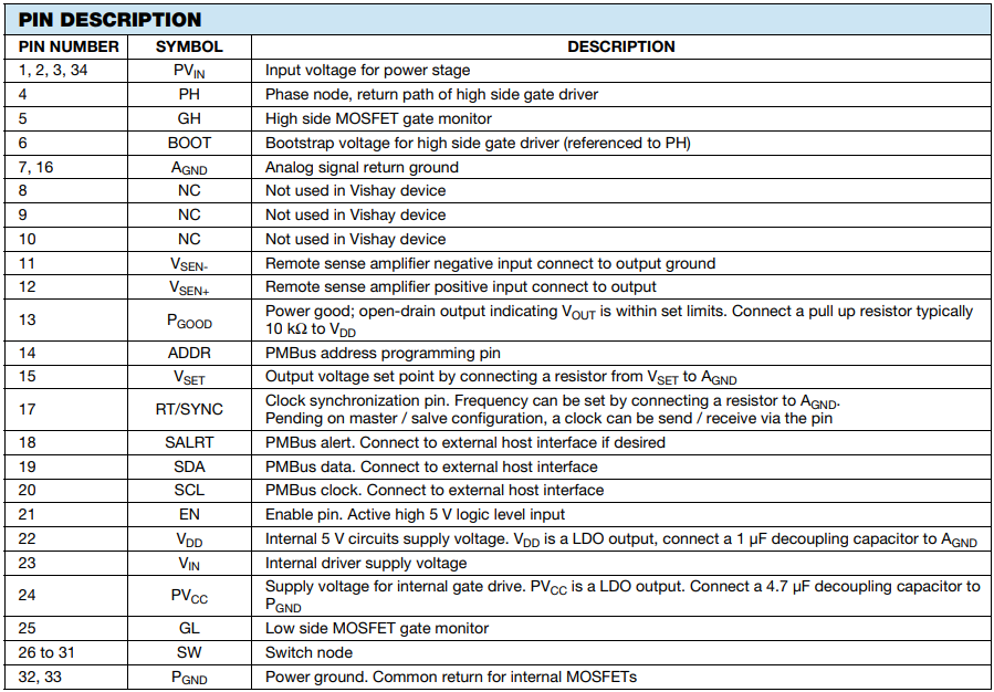
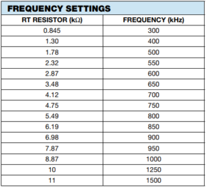
We can quickly skim through the pin description table, to get an overview of what pin does what. For example, we can see in figure 4, that the RT/SYNC pin does set the switching frequency. It doesn’t say what value resistor we use though. For that, we can refer to the “RT/SYNC PIN and Mode of Switching Configuration” section within the Operational Description. Figure 5 below shows the table within that section. It lists the resistor value for each switching frequency of interest.
Functional block diagram
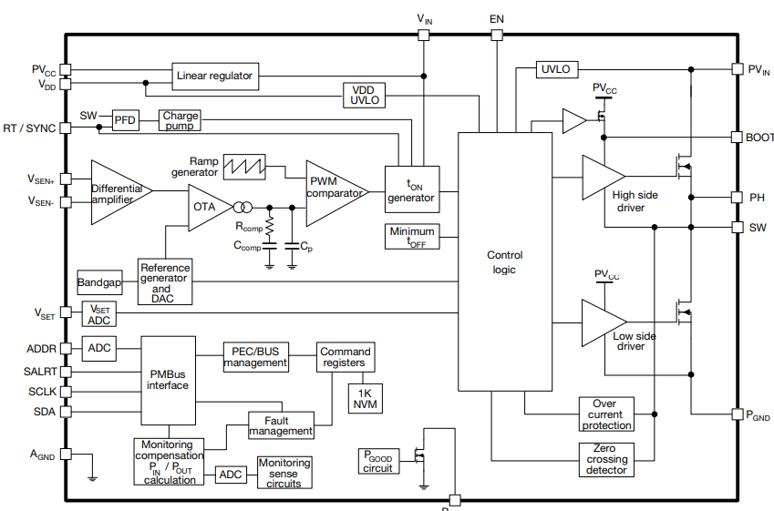
Something that nearly all datasheets will have is a block diagram. The SiC45x’s is shown in figure 6. I don’t always reference them, but when you do need them, it is really nice to have as a reference. They can be helpful in determining:
- How separate grounds are connected.
- What type of driving circuitry a part uses.
- How to bypass sections of the part.
- How internal voltages are generated.
- Many other fundamental items.
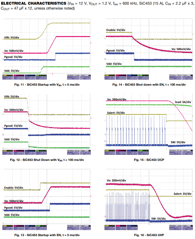
What about all those charts?
The SiC45x datasheet contains over 9 pages different charts! Figure 7 below shows just one of these pages. I honestly don’t tend to focus on them too often. Going through charts doesn’t make it into my standard workflow when reading datasheets. There are certainly times however, that they help, especially seeing startup behaviors. So for me, they are similar to the block diagram, being nice to have when you need them!
PCB Layout Recommendations
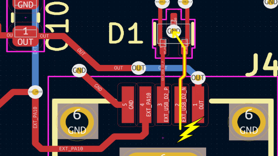
Now we come to the section that explains why I chose the part that I did for this article! Most IC’s don’t have a specific PCB layout section unless the layout is crucial to its operation. A switching regulator may be the most direct example of a part that requires a solid layout. Figure 8 below shows the first of three pages on the layout recommendations. I honestly don’t remember ever seeing a datasheet that has three pages discussing the layout. That is a really nice thing to have, and I wish more manufacturers would include that much detail!
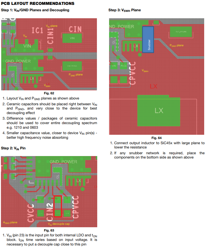
There is something I mention in nearly every design video or livestream I do. Do not treat datasheet PCB layout recommendations as requirements. Often, manufacturers while meaning well, won’t actually give great advice. So, if they have a layout recommendation section, this is what I do. I will 100% reference it, but just use it as a baseline. I then will make adjustments to it as I see fit. (Typically the words they say are valid, but they will do goofy things in the images of their layout.)
Never forget the errata!
Something that can be critical when reading datasheets is to understand what an errata is. When a datasheet is first published there are often errors in the print. As time goes by, engineers report these errors to the manufacturer, or they find them internally. They will then fix the error, and mention this at the end of the datasheet in the errata. This also means, you must always make sure to have the most up to date version of the datasheet. Don’t trust DigiKey/Mouser/etc, for a crucial part, get the datasheet directly from the manufacturer’s website!
Other times (Especially with MCU’s) they will publish a second errata document that highlights the errors within the original datasheet. Also, these errata’s will sometimes show issues with the physical IC. An example is if a custom MCU should have 8 ADC pins, but one of those pins isn’t currently working as one. They would list in the errata that pin xxx is not functional as an ADC, and will be fixed in a later revision.
Conclusion
The goal of this article was to breakdown how I handle dissecting a new datasheet. While every datasheet is slightly different, there are generalities that exist between them all. Using the SiC45x as an example, I highlighted the key points to look for within the document. Hopefully these tips will make reading a datasheet in the future a breeze!
MicroType Engineering is a full service electronics design firm. We offer turnkey support including PCB design, firmware, and prototype/small-batch assembly. Please reach out to learn more!


.webp)