
When designing a lithium ion battery charger circuit, you will find that, like nearly everything in electronics design, there is no perfect solution. It is always about weighing the pros and cons of a specific scheme, then deciding which works best for your design. We design custom battery management systems that incorporate these considerations, and this article walks through the key tradeoffs.
Notes About This Article
For the sake of conciseness, my example schematics will not be functional, aiming to only show a high level system view. When a LI-ION CELL is shown, it is assumed that the cell will have all proper safety protection circuitry built in to it.
What Not To Do
When designing your first lithium ion battery charger circuit, your first instinct is likely to do something like the below image:
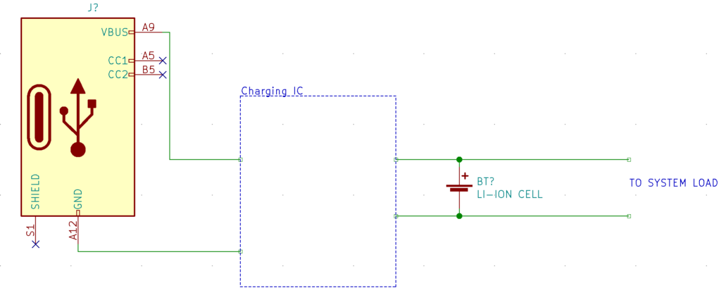
Many lithium ion battery charger datasheet’s actually encourage and suggest this very scheme.
While this setup may work in certain scenarios, it is not a good idea for the majority of designs. The reason is simple: If your charger’s output directly connects to the battery
and the rest of the system load, it is unable to detect the current that is going into the battery. This issue worsens if your system draws a large enough load to start sagging the voltage rail itself. This can skew the entire battery charging algorithm.
The primary issue is in the final portion of the charging algorithm. The IC senses the charge current to know when to stop charging. If the system load is drawing current, the charger may never turn off, damaging the battery.
The rest of this article will discuss three options that, while more complex to implement, are much safer and more effective.
1. Disable The System Load While Charging
The easiest lithium ion battery charger circuit is simply disabling the system output when charging. This is common in a lot of products you encounter in your daily life. That is especially true for products that draw a lot of current while in use, like portable vacuum cleaners. The easiest way to implement this is to simply use a MOSFET in series with the battery going to your system load. The input power supply controls the gate of the MOSFET. When you plug in the power supply, the MOSFET turns off, disconnecting the system load.
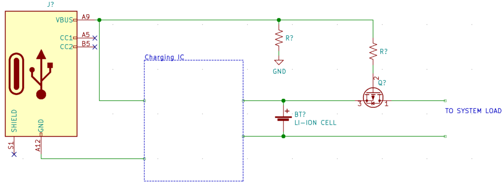
Since the system load only has power when not charging, the rest of the system design becomes easier. You don’t have to worry about handling situations differently based on what power source you are currently using.
Pro’s
- Only requires a single primary component.
- Quickly charges the battery, since the charger only supplies power to the battery.
- You only need to worry about the circuit when it is under battery loading conditions.
Con’s
- Does not allow the system to be used when charging.
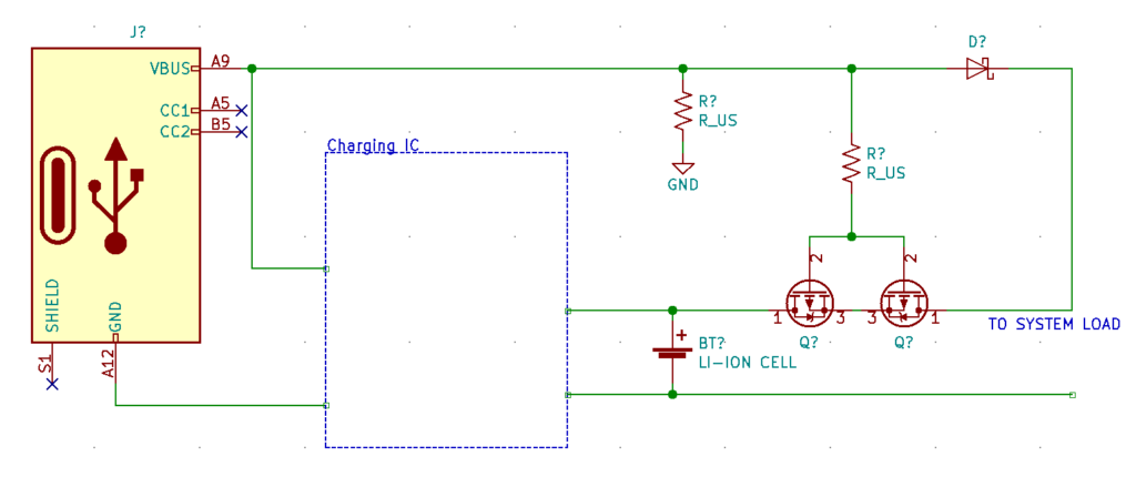
2. Have The Load Take Input Power While Charging
This lithium ion battery charger circuit is very similar to the previous, with two differences. First, instead of just using the MOSFET, you also pass the input supply to the load through a diode. By connecting the FET gate to the input power supply and a diode (normally a Schottky) in series, the system load takes power from the input supply while charging. The diode is required to prevent backfeeding of the battery to the input source. You can replace the diode with a MOSFET ideal diode to reduce the voltage drop.
The second change is to add an additional P MOSFET back to back with the other one. This prevents the input supply from directly charging the battery through the body diode.
An important consideration with this method is to understand the limitations of the source power supply.
As an example:
- A standard 5V USB is the main input, which can supply ~500mA.
- There is a 1000mAH lithium ion battery with a max charge rate of 0.5C (500mA), and max discharge of 1C (1A).
- The charging IC charges at a maximum of 300mA (this occurs in the constant current portion of the charge cycle).
- Depending on state, the load can use anywhere between 50mA and 500mA.
While not plugged in, the load is entirely on battery power, and there are no limitations. It is able to fully draw the 500mA. Plugging in the board for charging and while in constant current mode, the USB supply is supplying around 300mA. This means, there is only 200mA available for the rest of the system. Implementing proper downstream system design is imperative to prevent power supply damage.
This scheme nearly always requires you to feed the VUSB into the system microcontroller. This way, you can account for times when it is charging, to ensure that no overload situations occur.
Another item to consider with this method, is that the input supply voltage will likely be higher than the battery. If you are using a boost convertor after your battery to boost a single cell lithium battery to 5V, and are using a 5V charger, then there won’t be an issue. If instead, your system is just running directly off of the nominal 3.7V from the battery, you must account for the 5V that the system will see when charging.
Pro’s
- Not much more complicated than the prior method. Still only requires a few parts.
- Allows the system to be in use while charging.
Con’s
- The load is at risk of overloading the input charging supply, causing damage.
- The system must know when it is charging, complicating system design.
- Requires the system to account for the differences in voltage between the input supply and battery.
3. Load Sharing With a Power Path IC
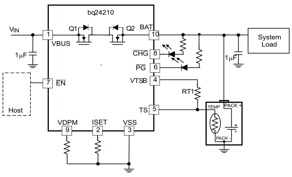
The final lithium ion battery charger circuit is the most advanced, and takes the advantages of the prior method, and removes the main con’s. There are battery charging IC’s made by Texas Instruments, Analog Devices, and Maxim that have what they call “Power Path” management.
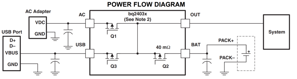
They incorporate the same style of MOSFET switches between the battery and system load like we previously looked into. Instead of simply cutting off the power when charging, they use DPPM (Dynamic Power-Path Management). This means that when charging, the IC will supply power to the system load from the wall supply, just like in my example 2. If the system load then draws more than the wall supply can source, it switches to allow the battery pack to make up the difference. Thus, a power path IC can supply the same power whether charging or not.
This simplifies the system design, as you don’t have to worry about the current limitations between the battery and the charging source. As long as the battery is able to source that much current, the IC will handle it.
They also have a lot of neat features, like instantly supplying power to the system load when charging, even when the battery is deeply discharged. One thing to be aware of, is most of these have the MOSFET built in to their silicone. You must be sure that the current limit for the IC is high enough for your use case. There are some that use external MOSFETs. This allows the selection of high-power MOSFETs.
Pro’s
- Allows the system to have power while charging.
- Removes the current constraint of the input charging supply.
- Allows the system designer to not worry about power supply, the IC handles it completely.
Con’s
- More expensive
- Smaller part selection
Conclusion
When designing a circuit with a lithium ion battery there are many things to consider. Often, how the battery shares the load with the charger is overlooked. This article discusses various lithium ion battery charger circuit’s for load sharing. With many designs, there is no need to use the device while charging. For this scenario, disabling the system load while charging is a cheap and simple solution. If instead, the system load needs power at all times, power must be sourced from the charger or battery. Depending on power requirements either sourcing power directly from the charger, or using an intelligent power path IC must be used.
MicroType Engineering is a full service electronics and mechanical product design firm. We offer turnkey support no matter how far along in the design process you are. We have full schematic capture, PCB design, firmware, mechanical design, and prototype/small-batch assembly services. Please reach out to learn more!


.webp)