
One of the first projects that aspiring electronic designers or engineers undertake is making an LED blink. Completing this task with a simple resistor to limit the current is relatively simple. Many people then believe that this is the standard “end-all, be-all” for LED control. For simple LED indicators and low powered lighting, driving LEDs linearly like this is fine, but many applications call for a different approach. In this article, I outline a few common alternative strategies and some unorthodox methods that we have used in the past for LED driver circuits. For tips on how to design the PCB for high power applications, check out our article on that topic here.
Primary Considerations
The main consideration when deciding on how to drive LEDs is how much power loss is acceptable. In battery-powered devices, this power loss equates to diminished battery life. In high-power LED applications, it equates to heat generated. Before choosing how to drive the LEDs, have an idea of how much power your design allows you to dissipate. That guides most of the decisions.
Another important consideration is how many different LEDs you are using. Not just the total, but how many different colors/types? The more variety, the more difficult it becomes, as it is harder to match forward voltages from one strand to another. Understanding the total number of LEDs also is essential in dictating the driving voltage to run them in series.
Linear Drive from a Microcontroller
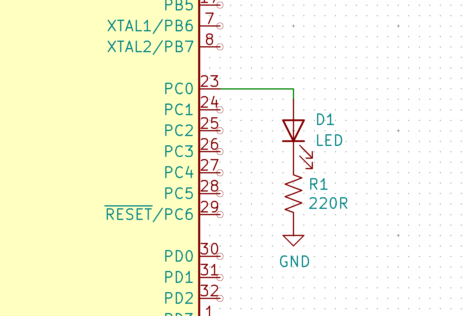
A linear drive circuit is any that dissipates all excess power in the form of heat. The most simple example of this is the LED-resistor circuit, as mentioned earlier. If the current supplied to the LED is minimal, then it can usually be directly driven from a microcontroller pin, such as an Arduino, as shown in Figure 1. The major disadvantage of any linear LED driver circuit is dissipating the excess power. It is also crucial to ensure that there is an adequate voltage “headroom” voltage to be able to drive the LEDs.
Linear Drive from A MOSFET
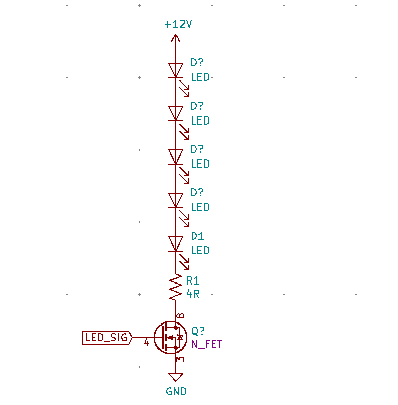
Figure 2 shows an LED driver circuit controlled by a low-side n-channel MOSFET to switch the LEDs on/off. The FET also allows for PWM dimming. Using Ohms law, and with the LEDs having a forward voltage of 2V each: V=IR, 12-(5*2) = I*4, I = 0.5A. So this simple circuit is driving the LEDs at 500mA, suitable for high-powered LEDs. The next step is to calculate the power dissipation: P=I^2 * R = 0.5^2 * 4 = P = 1W. Dissipating 1W is a lot for a single resistor, and requires a 2512 sized or larger surface mount resistor.
For help with selecting the right MOSFET for your LED application, see our guide on that topic.
Another option that we have used with great success in linear based LED circuits, is to split up the current limiting resistors. Instead of using a single 4R resistor, two 2R would be used in series, dividing the power dissipation evenly between them, using 1210 resistors instead. It also allows strategic placement of the resistors on the board, spreading the heat out evenly. Figure 6 shows how splitting up the resistors works with different LEDs.
Linear Drive From a Constant Current Source/Driver
Many “integrated” LED drivers supply a constant current to an LED strand. These drivers offer much convenience that a resistor driven circuit does not. It is important to note, however, that these drivers are still using linear technology. It is crucial to understand how much power the driver will be dissipating and to make sure it falls in a safe range.
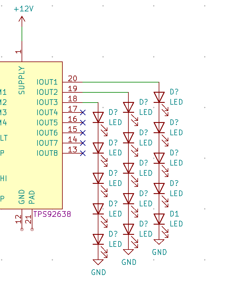
Figure 3 shows an example of a linear eight strand LED driver. The driver is controlling three strands of the same LEDs from the previous circuit. Temperature limits the maximum power the driver can dissipate. With a maximum temperature of 100c, it can dissipate around 1.8W maximum. The chip is also limited to a maximum of 70mA per strand. To calculate the power dissipated by the chip at 70mA, each strand: P=IV, P/3=0.07*(12-10), P=0.42W. 0.42W is well within the safe range for this chip, so it can be used as-is. If the power was too high, an option is to place a resistor on each strand. As long as the resistor is sized correctly, it will dissipate some of the power, while the chip dissipates the rest. That trick shown in figure 4 is quite useful when there are unbalanced strand lengths.
Constant Current from a Switched LED Driver
A switch-mode constant current LED driver operates similarly to a linear driver, except it uses a switching topography. This switching allows it to operate at upwards of 80%-90% efficiency. A significant disadvantage of switching drivers is that they tend to be expensive. Having any switching supply onboard also introduces unwanted switch-mode noise.
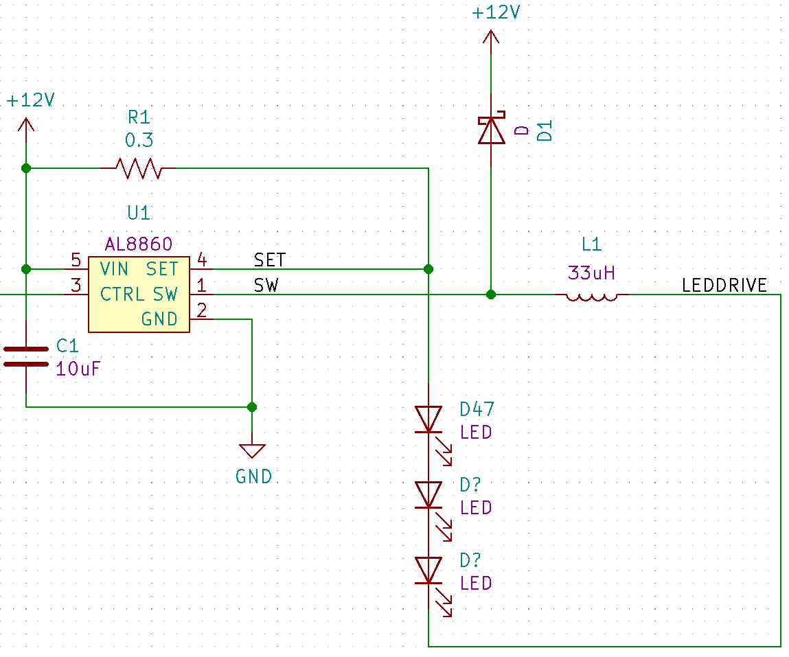
Figure 5 shows an AL8860 based switching LED driver circuit. It drives a single strand of LEDs from any voltage between 5V and 40V. Depending on the voltage supplied, and the voltage of the LEDs, this chip is capable of up to 97% efficiency at around 1A of current. Under ideal conditions, you can drive a strand of LEDs at 1A, while dissipating less than a tenth of a watt from the chip! That’s a substantial difference from the previous examples using linear technology. There are also buck-boost drivers that take 5V (for example) as an input and can drive LED strands up to 20V. They tend to not be as efficient as a drop-down regulator, but it is still an option to consider.
Real-World LED Driver Circuit Example
We have used an unusual method of driving LEDs with great success. It combines the linear drive and switch-mode drive to offer the benefits of both. It is especially useful when there are a lot of different LED colors.
For example, say we have 100 LEDs to drive at 1 amp each, with 5 different colors. The input power supply is 24VDC, with separately controllable colors. We need to drive 28 reds (forward voltage = 2.1V), 20 amber (Vf = 2.5V), 10 yellow (Vf = 2.8V), 22 green (Vf = 2.5V), and 20 white (Vf = 4V). Yes, this is an extreme example – both in the power required, and in the number of LEDs – but we recently designed a board similar to this!
That’s a lot of Drivers!
When driving LEDs at 1A, the obvious first choice to drive them is by using a switching LED driver circuit. An issue that arises with this approach is that at this high of power, switching drivers will only be able to drive a single strand each. That means we would require a lot of drivers on this board. The more switching drivers on board, the more switch-mode noise produced. Splitting up the strands gives us:
- 11 RED, 23.1V
- 11 RED, 23.1V
- 6 RED, 12.6V
- 9 AMBER, 22.5V
- 9 AMBER, 22.5V
- 2 AMBER, 5V
- 8 YELLOW, 22.4V
- 2 YELLOW, 5.6V
- 8 GREEN, 22.5V
- 8 GREEN, 22.5V
- 6 GREEN, 15V
- 5 WHITE, 20V
- 5 WHITE, 20V
- 5 WHITE, 20V
- 5 WHITE, 20V
The thought of having 15 different switch-mode LED drivers on a single PCB is sure to give anyone with EMC experience nightmares! While it is absolutely possible to drive them like that, it will require extensive filtering, ensuring no coupling of switch-mode noise on the power rails. For this project, a large heatsink would be on the back of the board. While we wanted to limit the heat generated, we had some flexibility with our design. I would rather deal with the heat, than deal with 15 switchers!
Driving all strands linearly from 24V would involve enormous amounts of power dissipation, more than would be possible, especially on the short strands. For example, strand number 6: P=IV=1A*(24V-5V)=19W. Good luck finding a standard resistor or linear driver to dissipate 19W of power!
Alternative Solution
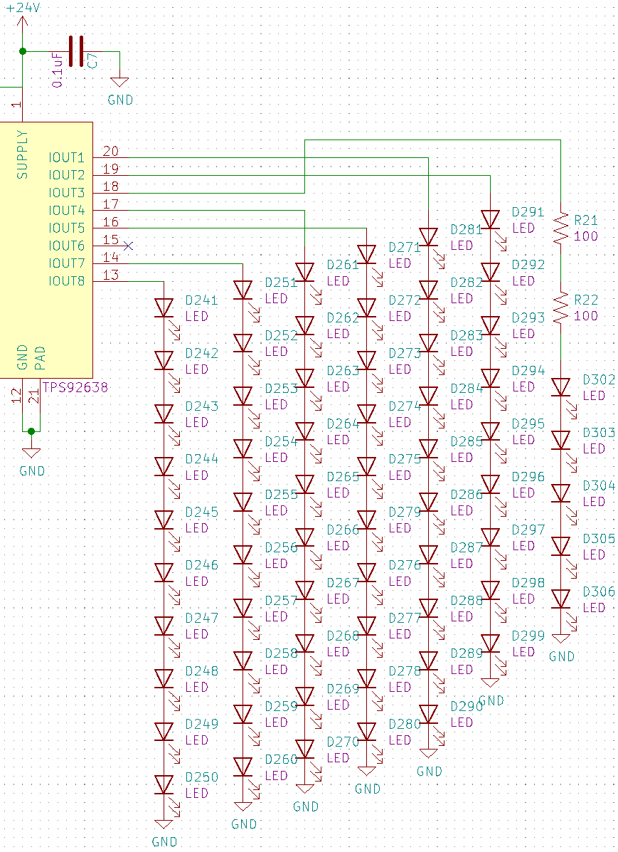
What we decided on was to first drive the long strands directly from the 24V rail with a linear drive using resistors. Strands 1, 2, 4, 5, 7, 9, 10, 12, 13, 14, and 15 are all driven from 24V. The white strands dissipate the most power: P=IV=(24-20)*1=P=4W. Using 2010 sized resistors which can dissipate 2W each (3502, CGS series), 3 1.3R resistors are used on each strand, with each resistor dissipating around 1.3W. One of these strands is shown below in figure 6.

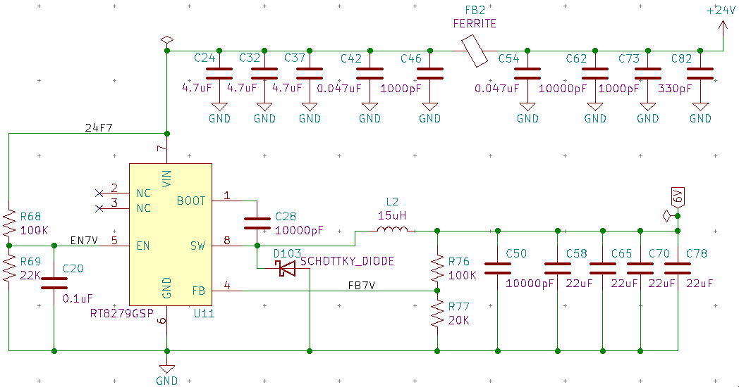
Strands 3, 6, 8, and 11 are left and are too short to drive directly from 24V. What we did was use two switching buck regulators to drop down the 24V rail to a 6V and a 16V rail. The 16V rail directly drives strands 3 and 11 while the 6V rail drives 6 and 8.
Conclusion
It is impossible to have a “one size fit’s all” approach with circuit designing. The same is true when driving LEDs. This article outlined several methods that can be used to drive LEDs, depending on the circuit parameters. If high efficiency is required – both in battery life or heat dissipation – a constant current switching LED driver is the obvious choice. If simplicity is key, then a linear drive approach may be a good option, either using resistors, or a dedicated LED driver. Debugging tricky power electronics is part of what we do. MicroType Engineering provides custom electronics design services including LED drivers, power supply design, and thermal management. Contact us to discuss your project.


.webp)